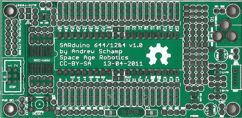
Introduction
This page contains the (relatively unchanging) information about v1.0 of the SARduino644 board.
Updates
This revision was created to address the errata from v0.1, as follows:
- The reference designators were corrected and gaps removed.
- We labeled as many passives as we could.
- We separated the breakout area from the microcontroller pins, for more flexibility in how to use the breakout area.
- We added additional breakout for the FTDI cable input, as well as a simple auto-reset circuit and selection jumper.
- We slipped in extra power and ground rails wherever there was space.
- We added breakout space for raw VIN, safe VIN, and VCC in.
- We repositioned the bypass caps, and added pads for optional 805 bypass caps as an alternative.
We are very happy with how the improved prototyping area turned out, and the auto-reset circuit has proved its worth already.
Design Files
Because we had this round made as a 2-board panel on a 10cm x 10cm board from Seeed, we’ve included the panelized gerbers, along with the single-board gerbers we used to construct the panel. If you order a board, don’t be surprised to see the edge where the panel was separated, though it should be a clean cut.
| REVISION | DESIGN FILES | SCHEMATIC | PCB | GERBERS |
|---|---|---|---|---|
| SARduino644 v1.0 | everything (.zip) | .sch .png | .brd .png | single.zip panel.zip |
Bill of Materials
Here is a Mouser BOM of all the parts listed below, for easy ordering.
| DESIGNATOR | VALUE | PURPOSE |
|---|---|---|
| S1 | 40-pin IC Socket | 0.600″ wide, 0.1″ pitch |
| IC1 | ATmega644P | Microcontroller (or ATmega1284P) |
| R1 | 10K ohm | Pullup resistor for RESET switch |
| Y1 | 16MHz Crystal | Oscillator (or 16MHz Ceramic Resonator, omit C1,C2) |
| C1,C2 | 18-30pF Cap | Capacitors for Crystal (match required value) |
| C3,C4 | 0.1uF Cap | Bypass capacitors for MCU, consider putting right at 5V/GND and A+/GND pins instead of labeled positions |
| FTDI | 1×6 header | 6-pin FTDI cable programming connection (optional) |
| SV1 | Reset button | 6mm x 6mm tactile momentary switch |
| PWR-SEL | 1×3 header | 3-pin power selector (external or USB) |
| ICSP | 2×3 shrouded header | Standard AVR ICSP header |
| SW1 | Reset button | 6mm x 6mm tactile momentary switch |
| C7 | 0.1uF ceramic capactior | For auto-reset circuit |
| JMP1 / JMP2 | 0.1″ jumper | To enable / disable auto-reset, and for power selection. |
| EXTERNAL POWER SUPPLY OPTION: | ||
| D1 | 1N400X | Input protection diode (e.g., 1N4001 or 1N4004) |
| PWR-JACK | 2.1mm jack | External Power Jack |
| VR | 7805 | 5V Regulator (any IN-GND-OUT should work, or 3V3 if you want that) |
| C5,C6 | 10uF-100uF | Power Supply Filter Caps |
Errata
- The silkscreen, especially on the reverse side of the boards, is a bit smudged. Some of it is hard to read because it is so tiny, in other cases, I think it’s the smudging. That’s just how they came from Seeed, I’ll make an inquiry, but I don’t expect much to come from it. In the future, maybe cut down the line width, and increase the text size, where possible.
- Some of the labels for the bypass caps are hidden beneath the socket. I did this on purpose, but now I’m having second thoughts.
- The FTDI connector, the external power jack, and the voltage regulator need to be labeled on the silkscreen.
- An (optional) power LED circuit would be nice.
- The power supply filter caps and the voltage regulator, when placed, make accessing the SC-70 breakout very difficult. If you intend to use that breakout, please consider populating it before the power supply circuit.
- None of the vias are tented, we’ll have to see if there’s some way to do that. Maybe the vias were too large.


Pingback: SARduino644 v1.0 Prototypes | Space Age Robotics
Pingback: vulussu» Blog Archive » SARduino644 v1.0 | Space Age Robotics
Hello,
i’ve got an usbtinyISP and i’ve read that this programmer can’t burn an optiboot on an avr like 1284p !
have you a solution to do it?
With an arduino as isp?
I try to wire vcc, gnd and reset from the holes near the µC on the board, and pin 11,12, 13… as in the arduino tut.
http://arduino.cc/en/Tutorial/ArduinoISP
when i try to burn,i’ve got an error about “signature”
I use https://github.com/maniacbug/mighty-1284p to have a description board to arduino…
please help!
Ok sorry i’ve found the mistake
the pin to use on the board are 5,6,7 reset, vcc and ground, the 6 pins follow on the board.
my old arduino (ng/168) do the job…
I’m glad you got it going. I like your write-up, thank you for the kind words. Is there a reason you didn’t use the ICSP header to program the bootloader?
Pingback: vulussu» Blog Archive » Sarduino: AT1284p + bootloader